Documentation of the Internal Electronics and the Power Supplies
Powering System
- For switching check switches and buttons.
- For more information about the batteries check the battery system.
PC
Power Path: The PC power pass through the base board, which powers the PSU, which in turn powers the motherboard.
Power Source: The power comes from either the PC battery or an adapter connected to an ac plug. The adapter overrides the PC battery when connected and powers on the base board.
Motor
Power Path: The motor power pass through the anti-spark switch which powers the VESC, which in turns control the motor.
Power Source: Two li-po 7.4 V batteries connected in series.
Battery System
There are two independent battery systems on the vehicle.
PC battery
The battery has 6 series li-po cells with a total nominal voltage of 22.2 V. The PC battery poles are to be connected directly to the respective poles of the charger through the charging dean socket.
Motor batteries
There are 2 motor batteries, each with 2 series li-po cells, connected in series. Their total nominal voltage is 14.8 V. The positive pole of one battery and the negative pole of the other are connected directly to the charger respective poles through the charging dean socket. The remaining poles are connecting the two batteries together.
Switches and Buttons
There are two independent switches on the vehicle. One to turn on the PC and the other to turn on the motor.
PC
The PC switch connects or disconnects the PC battery +ve pole to or from the base board. Note that the negative pole is always connected to the ground of the board to close the circuit accordingly.
Motor
The motor button connects or disconnects the anti-spark switch device. The later device is directly connecting the external battery poles underlined in the battery system description to the VESC -Electronic speed controller- device. The VESC is in turn connected to the vehicle throttle motor.
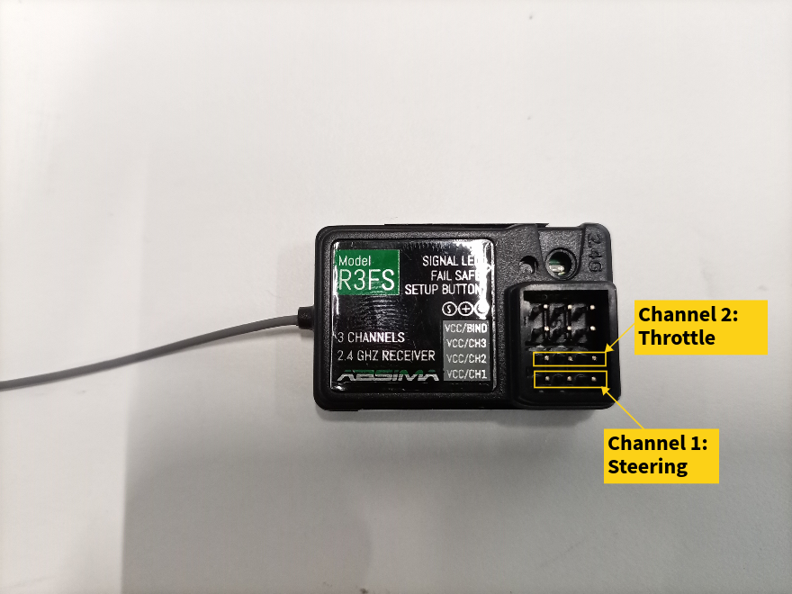
Joystick Controller and Receiver
-
The RF receiver has two channels. These are connected to the base board. The two channels are marked on the board as throttle and steering.
-
The base board outputs the processed input signals to the throttle motor through communication with the VESC and directly to the servo motor.
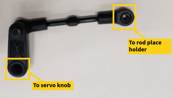
Servo Motor
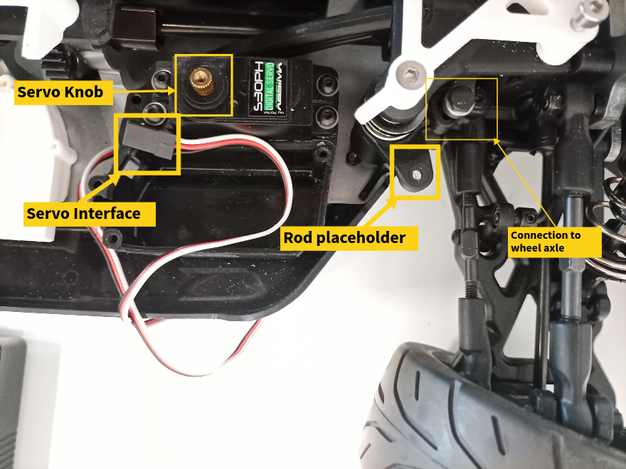
The servo motor has a rotating knob. A plastic flat rod is fitted on top of knob to connect the servo to the wheel axle mechanically.
To set the neutral angle of the wheel axle:
- Remove the plastic rod from the knob.
- Turn on the car to know the neutral state of the knob
- Rotate the wheel axle to the desired position.
- Reconnect the plastic rod. The rod can be elongated or shortened by rotating it around its axis.
System Description
The vehicle can be controlled by an RF joystick. It has a base board to route power, send and receive control signals. It additionally has an electronic speed controller that manages the higher power needed to run the motor by receiving the communication signal from the base board.
Components Functionalities
Base board
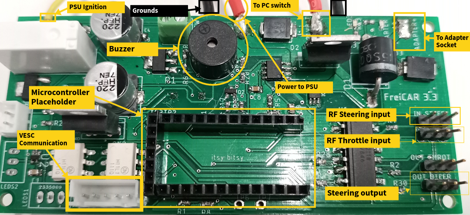
- Processes and controls signals through a mounted itsy-bitsy arduino microcontroller.
- Raises different alarms through a mounted buzzer.
- Receives the input throttle and steering signals from the RF controller.
- Sends the output communication signal to the electronic speed controller.
- Sends the output steering signal to the servo motor.
- Acts as the first routing stage for the input power (Adapter or PC battery through the switch).
- Sends the ignition signal and power to the PSU.
- Measures current (not currently used)
Arduino Microcontroller
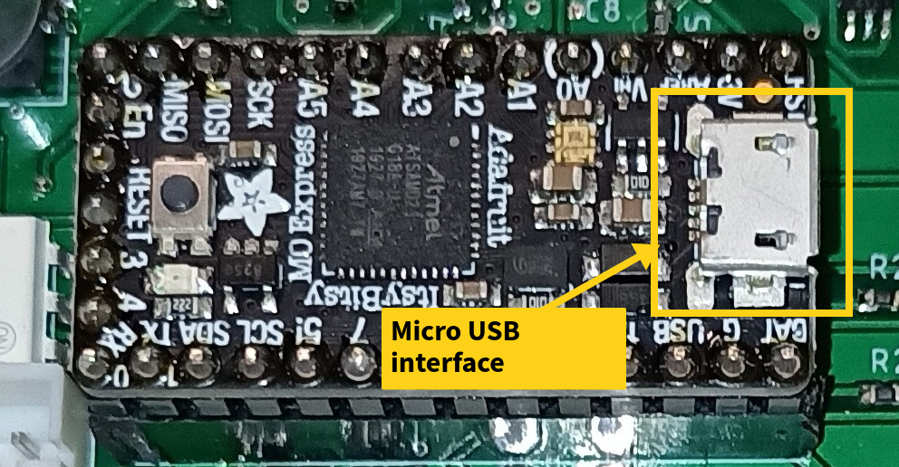
Mounted on the base board and connected to the PC using USB.
- Responsible for processing the communication signal sent to the electronic speed controller.
- Controls the buzzer alarm system:
- Raises an alarm with a certain frequency for a dropped communication with the electronic speed controller.
- Raises a lower frequency alarm for warning against low battery charge state.
Motherboard
- Interfaces all the PC components and the GPU.
PSU
- Routes different levels of power to the motherboard through two groups of cables:
- 24 pin power connector.
- 4 pin 12 V connector for the fan.
- Switches on the motherboard through a two jumper switch.